

Piping Design & Drafting Services for Process and Plant Industries
DevWorks piping design and drafting delivers piping layouts and isometrics for engineering teams—not mechanical part production drawings or electrical schematics.
Whether you are building a greenfield process unit, retrofitting an existing plant, or converting legacy drawings into intelligent 3D, we turn process requirements into constructible documentation your fabrication and construction teams can build right the first time.

What Our Piping Design and Drafting Services Include
We cover the full piping engineering scope for process and plant projects: process diagrams, 3D plant modeling, pipe stress analysis, support design, fabrication isometrics, and as-built documentation. Order a single deliverable or the complete package.

P&ID & PFD development
Process flow diagrams and piping & instrumentation diagrams that capture process logic, instrumentation, control philosophy, and safety interlocks. Drawings are developed from your process data, equipment data sheets, or marked-up redlines and kept consistent with the 3D model as the design develops.
3D piping modeling
Intelligent, specification-driven 3D models in AutoCAD Plant 3D, PDMS, and SP3D. Every model is clash-checked against equipment, structure, and other disciplines and is ready for design review walkthroughs before a single pipe is welded on site.
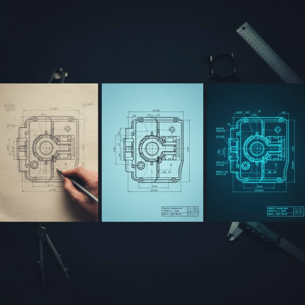
Piping isometric drawings
Fabrication-ready isometrics with spool numbers, weld locations, dimensions, flow direction, material specs, and full Bill of Materials. Isometrics are extracted directly from the 3D model, so dimensions, spool breaks, and BOM quantities always match the approved design.
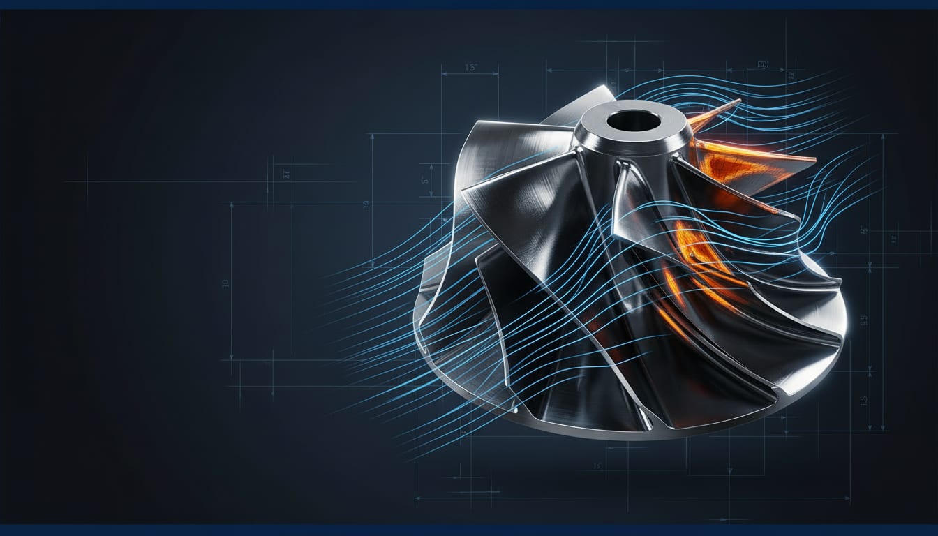
Pipe stress & flexibility analysis
CAESAR II and CAEPIPE analysis for thermal expansion, pressure, vibration, seismic loads, and equipment nozzle limits. Critical lines are checked against ASME B31.3 or B31.1 allowables and equipment nozzle limits, and results are delivered in a stress report with support recommendations. Equipment-level checks can extend into our advanced simulation services.

Pipe support design
Custom-engineered primary, secondary, spring hangers, guides, and anchors, designed in 2D and 3D in line with ASME B31.3 and MSS-SP-58. Support types and locations are coordinated with the stress analysis, so every critical line is supported where the analysis requires it.

GA & layout drawings
General arrangement drawings showing strategic placement of equipment, piping, and structural elements, coordinated across all disciplines. Plans, sections, and elevations are extracted from the 3D model, and our 2D drafting services team handles standalone drawing updates and redline revisions.

Material take-off & BOM
Accurate quantity take-offs and Bills of Materials extracted directly from 3D models, eliminating procurement shortages and over-ordering. Quantities come from the same model as the isometrics, the same principle behind our BOM automation and validation work.
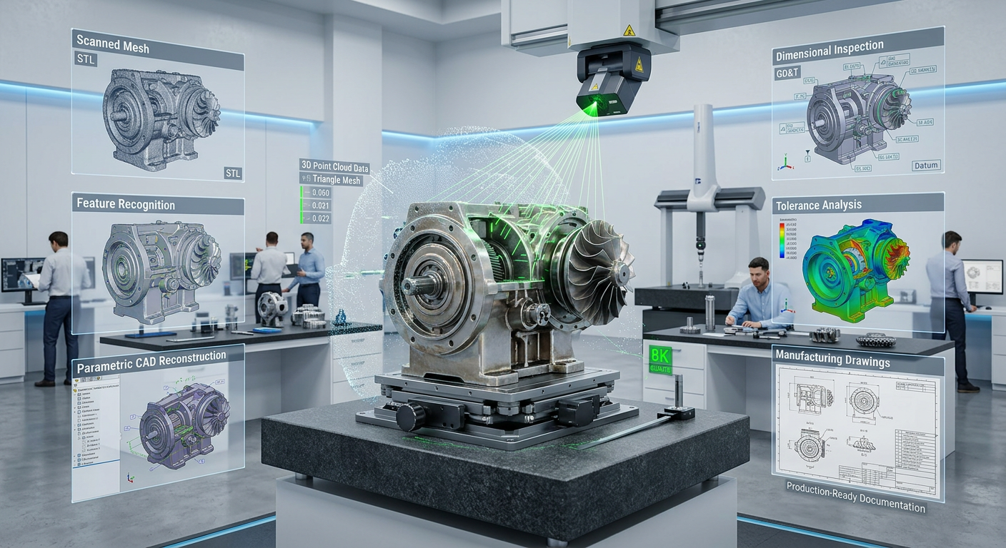
As-built & legacy conversion
Conversion of paper drawings, scanned PDFs, and 2D legacy files into intelligent CAD/3D, preserving historical assets for brownfield projects. Where drawings are missing or outdated, on-site laser scanning and point-cloud processing capture the plant as it exists today, supported by our reverse engineering team.

Plot plans & equipment layouts
Strategic equipment placement optimized for process flow, safety clearances, maintenance access, and future expansion of the plant. Layouts start from early conceptual design studies and are approved before 3D modeling begins, so routing and access issues are solved on paper, not on site.
P&ID & PFD development
Process flow diagrams and piping & instrumentation diagrams that capture process logic, instrumentation, control philosophy, and safety interlocks. Drawings are developed from your process data, equipment data sheets, or marked-up redlines and kept consistent with the 3D model as the design develops.
3D piping modeling
Intelligent, specification-driven 3D models in AutoCAD Plant 3D, PDMS, and SP3D. Every model is clash-checked against equipment, structure, and other disciplines and is ready for design review walkthroughs before a single pipe is welded on site.
Piping isometric drawings
Fabrication-ready isometrics with spool numbers, weld locations, dimensions, flow direction, material specs, and full Bill of Materials. Isometrics are extracted directly from the 3D model, so dimensions, spool breaks, and BOM quantities always match the approved design.
Pipe stress & flexibility analysis
CAESAR II and CAEPIPE analysis for thermal expansion, pressure, vibration, seismic loads, and equipment nozzle limits. Critical lines are checked against ASME B31.3 or B31.1 allowables and equipment nozzle limits, and results are delivered in a stress report with support recommendations. Equipment-level checks can extend into our advanced simulation services.
Pipe support design
Custom-engineered primary, secondary, spring hangers, guides, and anchors, designed in 2D and 3D in line with ASME B31.3 and MSS-SP-58. Support types and locations are coordinated with the stress analysis, so every critical line is supported where the analysis requires it.
GA & layout drawings
General arrangement drawings showing strategic placement of equipment, piping, and structural elements, coordinated across all disciplines. Plans, sections, and elevations are extracted from the 3D model, and our 2D drafting services team handles standalone drawing updates and redline revisions.
Material take-off & BOM
Accurate quantity take-offs and Bills of Materials extracted directly from 3D models, eliminating procurement shortages and over-ordering. Quantities come from the same model as the isometrics, the same principle behind our BOM automation and validation work.
As-built & legacy conversion
Conversion of paper drawings, scanned PDFs, and 2D legacy files into intelligent CAD/3D, preserving historical assets for brownfield projects. Where drawings are missing or outdated, on-site laser scanning and point-cloud processing capture the plant as it exists today, supported by our reverse engineering team.
Plot plans & equipment layouts
Strategic equipment placement optimized for process flow, safety clearances, maintenance access, and future expansion of the plant. Layouts start from early conceptual design studies and are approved before 3D modeling begins, so routing and access issues are solved on paper, not on site.
Industries We Serve
Our piping designers work on process and utility systems where code compliance, safety clearances, and constructability matter most.
Oil & Gas and Refining
Process piping, pipe rack routing, and tie-in design for refineries and gas processing facilities, including stress analysis for high-temperature and high-pressure lines.
Petrochemical
Piping layouts and fabrication isometrics for petrochemical units, designed to ASME B31.3 with multi-discipline clash detection before construction.
Chemical Processing
Piping design for chemical plants handling corrosive and hazardous fluids, with material specifications, supports, and routing planned around safety and maintenance access.
Pharmaceutical
Process and utility piping layouts for pharmaceutical manufacturing facilities, planned around tight equipment spacing, cleanability, and maintenance access.
Power Generation
Steam, condensate, feedwater, and cooling water piping designed to ASME B31.1, with flexibility analysis for thermal expansion and equipment nozzle loads.
Piping Design Service Models for Every Project Size
Choose the service model that matches your scope, from a single drawing revision to a full plant piping package or a long-term engineering retainer.

Line Modifications & Single Drawings
Drop us a P&ID, isometric, or layout — get clean drawings back. Best for one-off changes, line modifications, and plant retrofits.
Full plant piping package
End-to-end piping deliverables — P&IDs, 3D model, stress analysis, isometrics, BOMs — for greenfield refineries, chemical plants, and process units.
On-site survey & as-built
Our engineers come to your facility for laser scanning, point-cloud processing, and as-built drawing recreation — ideal for brownfield projects.
Piping engineering retainer
Dedicated piping capacity for ongoing programs, including sustainment work, debottlenecking, management of change (MOC) support, and drawing updates across multiple plants.
Pipe stress & analysis only
Hand off your existing model. We run the CAESAR II analysis, recommend supports, and deliver a signed-off stress report for your critical lines.
Flexible Engagement Options
Choose project-based delivery, a dedicated piping designer, or a fully managed service based on your timeline, budget, and IP sensitivity.

Project-based
Fixed scope, fixed price. Best for discrete piping projects with clear specifications and timelines.

Dedicated team
A dedicated piping designer or drafter exclusively assigned to your pipeline of projects.

Managed service
We handle scoping, modeling, drafting, and QC — you review and approve. End-to-end ownership of deliverables.
Our Piping Design Process, From P&ID Review to Fabrication Handoff
Every piping project follows the same five-phase process, so your team always knows what is complete, what comes next, and what needs your approval.
01
Discovery & scope alignment
We review your P&IDs, plot plans, equipment data sheets, and applicable codes (ASME B31.3, API, etc.) to lock in scope, deliverables, and timeline.
02
Conceptual layout & routing
Initial routing, equipment placement, and preliminary 2D layouts for early approval, so routing issues are resolved before 3D modeling starts.
03
Detailed 3D modeling
Intelligent 3D model development with full pipe spec compliance, multi-discipline clash detection, and milestone-based design reviews.
04
Stress analysis & optimization
Critical line analysis in CAESAR II, support optimization, and design refinement for thermal, seismic, and operational reliability.
05
Drawing extraction & QA handoff
Isometrics, GA drawings, MTOs, and BOMs are extracted from the approved model, then checked through multi-stage QC with full revision history before the fabrication-ready handoff.
Piping Design Software and Codes We Work With
We work in the platforms process plants and EPC teams already use, and we design every system to the codes that govern it.
Piping Design Software
AutoCAD Plant 3D
Specification-driven 3D piping models, P&IDs, and isometric extraction
AVEVA PDMS
3D plant modeling for large and multi-discipline process projects
Hexagon Smart 3D (SP3D)
3D plant design and model-based drawing deliverables
CAESAR II
Pipe stress and flexibility analysis for critical lines
CAEPIPE
Pipe stress analysis for thermal, pressure, seismic, and vibration loads
Codes and Standards
ASME B31.3
Process piping
ASME B31.1
Power piping
MSS-SP-58
Pipe hangers and supports
API standards
Applied as required by the project and equipment
ANSI and ISO standards
Dimensional, material, and documentation requirements
Frequently Asked Questions About Piping Design and Drafting
Our services cover complete piping system design, including 2D/3D layouts, P&ID development, isometric drawings, pipe stress analysis, material take-offs, and fabrication-ready documentation to support installation and manufacturing.
We work across oil & gas, petrochemical, chemical processing, pharmaceutical, and power generation industries, designing piping systems that meet the specific codes and operating conditions of each sector.
Yes. All our piping designs are developed in compliance with ASME B31.3, ASME B31.1, MSS-SP-58, ANSI, ISO, and API standards, with documentation packages that satisfy client and regulatory sign-off requirements.
Absolutely. We regularly handle brownfield projects, converting paper drawings, scanned PDFs, and 2D DWG files into intelligent 3D models and updated isometrics. We can also work from point-cloud data captured on-site.
We work in AutoCAD Plant 3D, AVEVA PDMS, Hexagon Smart 3D (SP3D), and pipe stress tools including CAESAR II and CAEPIPE, matching whichever platform your project or EPC partner already standardizes on.
We combine disciplined multi-stage QC checks, clash detection in 3D before any fabrication, and formal design review milestones at each phase to ensure every deliverable matches the agreed specification before handoff.
Yes. We support greenfield plant piping packages from P&ID through fabrication isometrics, as well as line modifications, retrofits, and debottlenecking work on existing brownfield systems.
Yes. We provide post-delivery support including revision management, as-built updates, and ongoing retainer capacity for plant modifications, MOC support, and debottlenecking work.