

Reverse Engineering Services for Precision Manufacturing
DevWorks reverse engineering brings an existing physical part back into accurate CAD for manufacturers—not early concept sketches before a design is frozen.
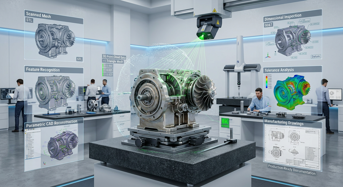
We capture geometry with non-contact structured-light, laser, and CT scanning, rebuild it as parametric CAD in SOLIDWORKS, CATIA, NX, Inventor, or Creo, and deliver GD&T drawings and deviation reports your manufacturing team can use from day one. Use it to reproduce a discontinued component, rebuild damaged tooling, or benchmark and improve an existing design.
Our Reverse Engineering Services
Our reverse engineering services cover every step from 3D scanning to finished CAD and drawings, so you work with one team instead of separate scanning, modeling, and drafting vendors.
3D scanning & digitization
We capture part geometry with structured-light, laser, and CT scanning, from hand-sized components up to 20 m assemblies. Scanning can happen at your facility or in our lab, depending on part size and whether the part can be moved.

Point cloud to CAD
We convert raw scan meshes and point clouds into clean, parametric, feature-based CAD models editable in SOLIDWORKS, CATIA, NX, Inventor, and Creo. Unlike a raw mesh, a feature-based model has a usable feature tree, so your engineers can change dimensions and release new revisions.
GD&T drawings
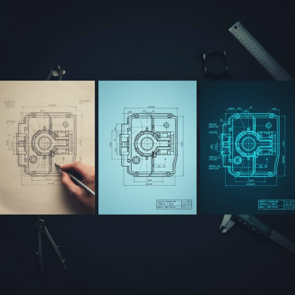
We create production-ready 2D drawings with datum reference frames, tolerance stacks, and inspection callouts aligned to ASME Y14.5. Tolerances are based on how the part functions in its assembly, not only on the measured size of one worn sample.

Deviation & inspection reports
We compare the finished CAD model against the scan data and deliver color-mapped deviation reports, first-article inspection support, and tolerance verification for quality sign-off. The report shows exactly where the model matches the physical part and where design intent was applied.
Legacy part recreation
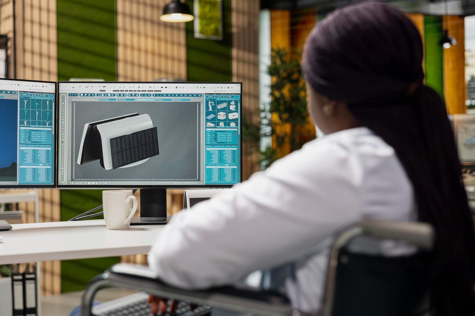
We recreate discontinued, obsolete, and undocumented components when the original manufacturer can no longer supply them. You receive DMSMS-ready CAD and drawing packages that let you source replacement parts and keep legacy equipment running.

Design optimization & DFM
Reverse engineering does not have to stop at an exact copy. We can refine the reverse-engineered model for manufacturability, weight reduction, or additive manufacturing before it goes into production.
How Our Reverse Engineering Process Works
Every project follows the same six steps, so you know exactly what happens between the first conversation and receiving production-ready CAD and drawings.
We confirm what the part needs to do: a drop-in replacement, a design improvement, or a tolerance study. We document its function, critical dimensions, material, and mating parts with your engineers before any scanning starts.
Based on part size, material, and feature complexity, we choose structured-light, blue-laser, or CT scanning, and decide whether scanning happens at your facility or in our lab.
We scan the part from every required angle, including internal features with CT where needed, to capture complete geometry without touching or damaging the part.
Raw scan data is cleaned, merged, and aligned to a coordinate system so datums and critical features are positioned correctly before modeling.
We rebuild the part feature by feature in your preferred CAD platform, with a clean feature tree your engineers can edit. Where a worn or damaged sample differs from the original design, we model the design intent instead of copying the wear.
We validate the model against the scan with a deviation analysis, then deliver GD&T drawings, native CAD files, and a written design-intent document for manufacturing and future changes.
Service Models That Fit Your Project
Pick the engagement shape that matches the scope — from single parts to long-term reverse engineering retainers.
Single-part reverse engineering
Ship us a part, get CAD and drawings back. Best for legacy replacements and one-off reproduction.
Flexible Engagement
Project-based, dedicated teams, or fully managed — pick what works for your timeline and IP sensitivity.

Project-based
Fixed scope, fixed price. Ideal for discrete reverse engineering jobs with clear deliverables.
- Defined SOW & acceptance criteria
- Typical 1–6 week turnaround

Dedicated team
A metrology engineer + CAD modeler + draftsman assigned exclusively to your pipeline.
- Full-time capacity
- Long or short engagement

Managed service
We handle scanning, modeling, and drafting under an SLA — you review and approve.
- Continuous output
- SLA-backed delivery
What You Receive with Every Reverse Engineering Project
Each project ends with a complete, manufacturing-ready package, not just a scan file.
Native parametric CAD
Feature-based models in SOLIDWORKS, CATIA, NX, Inventor, or Creo that your team can edit and revise.
GD&T manufacturing drawings
2D drawings with datums, tolerances, and inspection callouts aligned to ASME Y14.5.
Deviation report
A color-mapped comparison showing how closely the CAD model matches the scanned part.
Design-intent document
A written record of the part's function, critical dimensions, and the modeling decisions we made.
Assembly structure
For multi-part projects, a structured CAD tree with mated parts, interfaces, and exploded views.
Frequently asked questions
Reverse engineering services turn an existing physical part into accurate 3D CAD models and manufacturing drawings. DevWorks captures the part with 3D scanning, rebuilds it as parametric CAD, and delivers GD&T drawings and deviation reports.
Yes. Most reverse engineering projects start with only the physical part. We scan it, rebuild the geometry as editable CAD, and create new production drawings.
3D scanning captures a part's shape as a point cloud or mesh. Reverse engineering converts that data into a feature-based CAD model with design intent, tolerances, and drawings that can be used for manufacturing.
Accuracy depends on the scanning method, part size, surface finish, and the tolerances the part needs. We choose structured-light, laser, or CT scanning to suit each part and verify every model with a color-mapped deviation report against the scan data.
Most project-based work takes 1 to 6 weeks, depending on part complexity, the number of parts, and whether on-site scanning is needed. The timeline is defined in the statement of work before the project starts.
Cost depends on part size and complexity, the scanning method, whether you need parametric CAD or full GD&T drawings, and the number of parts. Project-based work is quoted at a fixed price, so send photos and rough dimensions for a quote.
We deliver native, parametric models in SOLIDWORKS, CATIA, Siemens NX, Autodesk Inventor, and PTC Creo, along with 2D manufacturing drawings.
Yes. CT scanning captures internal geometry in castings, composites, and sealed assemblies without cutting the part. For large equipment up to 20 m, our engineers can scan on-site at your facility.